FAQ
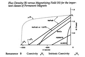
The Remanence Br determines the magnetic pull, generally the larger the remanence the stronger the pull.
The energy product BH max value, the bigger the energy product is, the smaller the size of the magnet you need.
The Coercivity Hc shows this. The larger the coercivity, the stronger is the magnet’s resistance to demagnetisation.
Neodymium Iron Boron alloy (NdFeB)
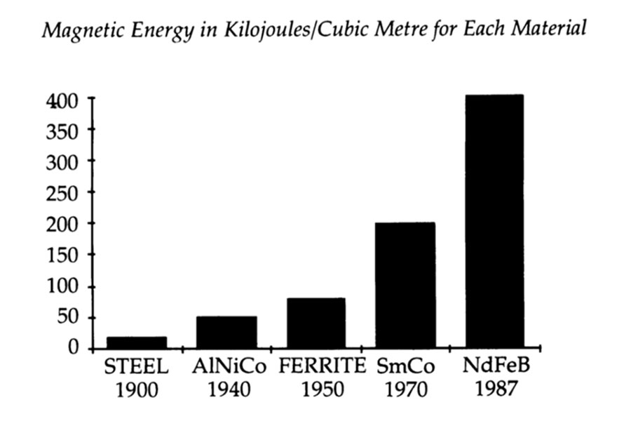
NdFeB magnets represent the latest and most significant development in permanent magnets for decades. Their superior magnetic properties are represented in these graphs.
Histogram of magnetic energy per cubic metre for steel AlNiCo Ferrite SmCo and NdFeB materials
Flux density B vs magnetizing field for the important classes of permanent magnets AlNiCo Ferrite SmCo and NdFeB
Because they have the highest remanence, coercivity and maximum energy product of all commercially available magnets. Which with these properties are proven to have the strongest pull, and the strongest resistance to demagnetisation, with the least amount of material needed that is available commercially.
The range of products which can benefit from the use of permanent magnet materials such as NdFeB (Neodymium Iron Boron) is enormous. We have already seen smaller, lighter, and more efficient units designed for applications in industries such as:
- Aerospace
- Automotive
- Medical
- Domestic
- Electronic and Instrumentation
Read more about various magnet applications here >
NdFeB magnets are currently marketed under two broad classifications:
- Bonded magnets: are usually isotropic with a maximum energy product up to 12 MGOE. These magnets are manufactured by compressing a mixture of NdFeB alloy flakes with a resin as a bonding agent followed by heat treatment to set the resin. The alloy flakes are made using a melt spun rapid quenching process developed by Delco Remy, a division of General Motors. The magnets are then magnetised as required.
- Sintered magnets: are anisotropic and have a typical maximum energy product in the range between 27 to 48 MGOE.
There are two processes for manufacture of high energy anisotropic Neodymium based rare earth magnets. One process uses melt spun isotropic crushed ribbon, hot pressed and plastically deformed which results in domain alignment and anisotropy.
The other process used widely is a classical powder metallurgical process. Cast alloy slabs, produced from molten alloy of the right composition are crushed mechanically to minus 3 mm in size and then milled to 3-5 µm powder.
The powder particles are magnetically aligned in an electromagnetic coil then pressed to shape in a mechanical or isostatic press. The pressed compacts are then sintered at 1100°C, finished to size by grinding or slicing, and magnetised in an electromagnetic coil at a very high magnetic field.
Whilst the basic process appears simple, in practice very strict controls at every operation must be maintained. Powder of the alloy is extremely pyrophoric, bursting into flames in contact with air. All operations must be carried out under inert atmosphere. Even a minute presence of oxygen will render powder useless. Other important parameters are particle alignment, particle size distribution and sintering parameters.
Basic Design Consideration
A few basic and often simple alterations to a magnetic circuit could result in a dramatic improvement in the results achieved from magnets.
- Magnetic flux lines always start at one pole and end at the opposite pole
- Magnetic flux lines take the path of least resistance
- Magnetic materials such as iron have a low resistance for magnetic fields
- The resistance to a magnetic field of air is about 1000 times higher than iron
- Air gaps in the path between the poles represent a high resistance to magnetic flux
- If the metal in a magnetic circuit is too thin it will saturate. Once metal saturates it is difficult to increase the flux in the circuit
- Flux lines will take the shortest air gap between poles
The following example illustrates how a simple change in the magnetic circuit increased the lifting force of a magnetic device by a factor of 15.
Let us consider the situation where a lifting device is made using the same magnet in two different arrangements. The magnet selected for the example has dimensions of 25.4 mm x 25.4 mm x 5 mm.
The first example shown in figure A utilises a single magnet with one pole face secured to a lifting attachment which is connected to a spring scale to measure the force on the magnet. The other face of the magnet is placed on a solid steel plate which is secured to a bench. The magnetic field holds the magnet to the steel plate.
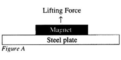
Figure A. Single magnet with one pole face secured to a lifting attachment
The magnetic force holding the steel plate to the magnet can be measured on the scale. The approximate force can also be calculated using the following formula:
F ˜ Bm2Am
8π x 10-7
where Bm is the magnetic flux density and Am is the area of the magnet contacting the steel plate (6.45 x 1O-4 m2). In this example the force of attraction is 41 Newtons. Bm would be about one third of the magnet’s maximum flux density of 1.2 Tesla because of the large air gaps in the circuit, say 0.4 Tesla.
Now in the second example as shown in figure B square steel section is used to complete the magnetic circuit between the upper side of the magnet and the steel plate significantly reducing the air gap. The steel section is secured to the upper face of the magnet and the scale. This results in an effective connection of both pole faces of the magnet to the steel plate.

Figure B. Single magnet with square steel section completing the magnetic circuit giving 15 times the force
Now the pulling force can be calculated using both surfaces contacting the steel plate with the following formula:
F ˜ Bm2Am + Bs2As
8π x 10-7
where Bs is the flux density entering the steel plate from the square steel section and AS is the surface area of the square steel section contacting the steel plate. In this case Bm will approach the maximum flux density of the magnet say 1.1 Tesla.
If we assume that Bm is equal to Bs and that As is equal to Am then the force will be 621 Newtons, which is approximately 15 times that of the original example.
So, 15 times the force without increasing the size of magnet.